Firefly – Simulated Heart Rate Monitor
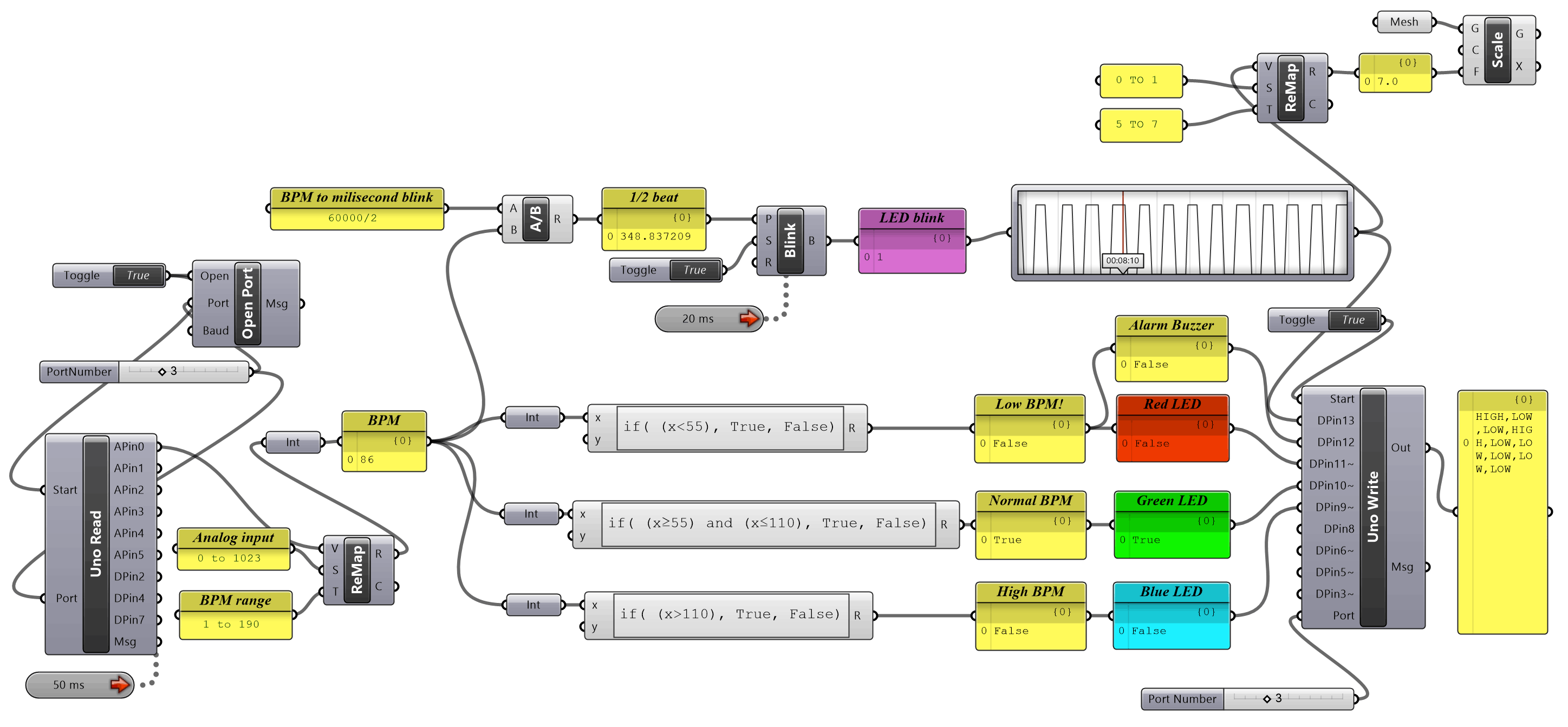
A simulated heart rate monitor using an RGB LED, Buzzer, LED and joystick connected to an arduino through grasshopper / firefly and controlling the scale of a 3D Rhino model. The analog joystick is used in place of a pulse sensor with it’s output remaped (remap numbers module) from 0-1023 (analog range) to 1-190 (heart beats per minute). The result is then fed into 3 conditional statements (expression modules) which turn on one of the LED colours depending on the value. The red LED condition also turns on the buzzer. The upper portion of the code takes the same remaped value and uses a division module to convert the value into a millisecond rate that pulses an LED through a binary blink module. For visual representation a value tracker module is used to display the beats per minute. The pulsing output then gets remapped to an appropriate value that changes the size (scale module) of a 3D model in Rhino that is linked with a mesh module. [Note: Change the video quality to 1080p if you are having difficulty making out details]
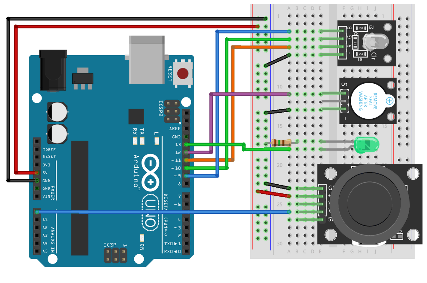
WIRING & GRASSHOPPER CODE
RGB LED module KY-016 – Contains a red/green/blue LED and suitable resistors. They have either a common cathode / GND or common anode / positive (not compatible with Firefly). [RGB LED B → D9, G → D10, R → D11, (-) → GND] Active Buzzer module KY-012 – This is the active version which generates it’s own tone when you apply power, the similar looking passive buzzer requires you to generate a tone. [Buzzer S → D12, (-) → GND] LED – A light emitting diode requires a resistor inline on either the + or – side to limit the current / brightness. [LED LED(-) → 150Ω → GND, LED(+) → D13] Joystick module KY-023 – contains 2 analog potentiometers (X axis and Y axis) and a button. [Joystick GND → GND, (+) → +5V, VX → A0]
0 Comments